TECHNICAL DATA
Potentiostat.fi battery analysers
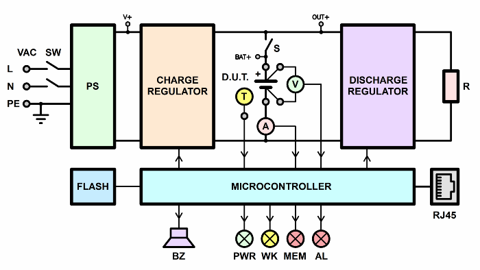
Battery analysers Potentiostat.fi series are a powerful tool for a variety of tests of cells, batteries, supercapacitors, supercapacitor modules, and any other chemical current sources.
Battery analysers Potentiostat.fi series tests various sources and energy storage devices, for example:
Potentiostat.fi series can provide a wide variety of operating modes. For example, charging, discharging, and cycling charging and discharging the battery. Testing is performed according to a very flexible test program.
Battery analysers Potentiostat.fi can perform many tests.
For example, the simplest, such as a single charge or a single discharge of the battery.
In addition, the instruments can perform cyclic tests, with multiple alternation of charge and discharge. This is relevant for resource and climatic tests of batteries.

Battery analysers Potentiostat.fi series can perform complex combination modes that simulate real-life battery conditions. For example, simulating the operation of an electric car battery when a car is moving in an urban driving cycle.
Potentiostat.fi battery analysers measures functions
During the tests, the Potentiostat.fi battery analysers measure:
The analyzer returns measurement results of the parameters of the tested battery in the form of text result files. In addition, software of device automatic plotts of charts of the charge discharge of the tested battery. Finally, software of analyzer automatically builds graphs of degradation of battery parameters (which is convenient, for example, during cycle-life tests).
Modifications of battery analysers Potentiostat.fi
Modifications differ in the following characteristics:
Battery testing
Battery testing on the Potentiostat.fi analyzer performs according to a user-configurable test program. The test program has very flexible settings. The user configures the test program before starting the test.
The battery test program may contain:
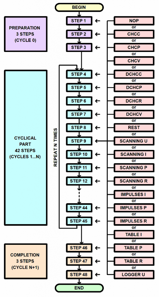
At each step of the testing program, the Potentiostat.fi battery analyzer can provide the following operating modes:
You can configure the repeating of the cyclic part of the testing program over a million times. Therefore, battery analysers Potentiostat.fi suitable for supercapacitors cycle-life tests.
Battery test modes on Potentiostat.fi analyzer
Potentiostat.fi battery analysers can provide multiple modes of operation with the battery under test. The variety is large.
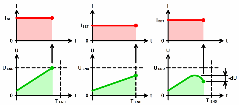
Charge with constant current
designed to maintain a given charge current regardless of voltage changes. Despite the increase in battery voltage, the charge current remains constant and equal to the specified current.
The step ends in the following cases:
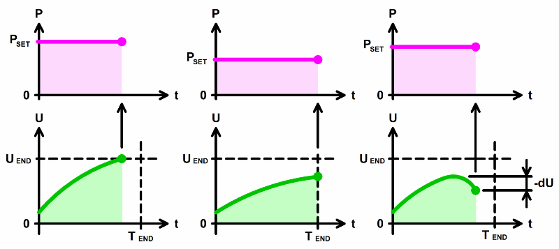
Charge with constant power
maintains a given charge power on the battery. As the voltage rises, the charge current will decrease in order to keep the power value at a given level.
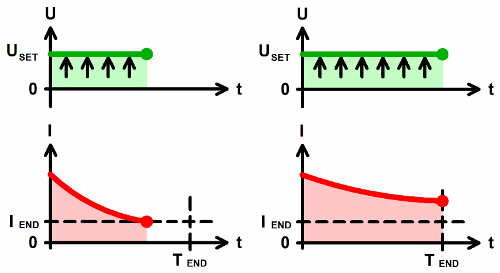
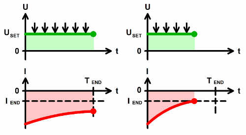
Charge at constant voltage
designed to keep the voltage on the battery at a given level after the main charge. The step, for example, helps to complete a two-stage charge in CC – CV mode. The end of the step occurs when the current drops to a predetermined value, as well as after a predetermined time.
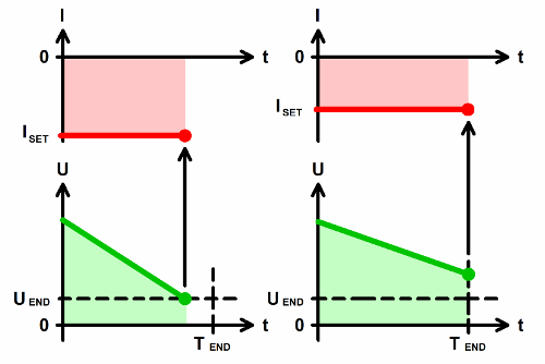
Discharge at constannt current
designed to maintain a given discharge current regardless of voltage. Despite the decrease in voltage, the discharge current remains constant and equal to the specified. The end of a step occurs when the voltage decreases to a specified value, or after a specified time.
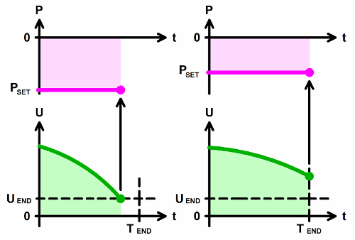
Discharge at constannt power
designed to maintain the specified discharge power. As the voltage decreases, the current will increase, so the battery discharge power will remain at the specified level.
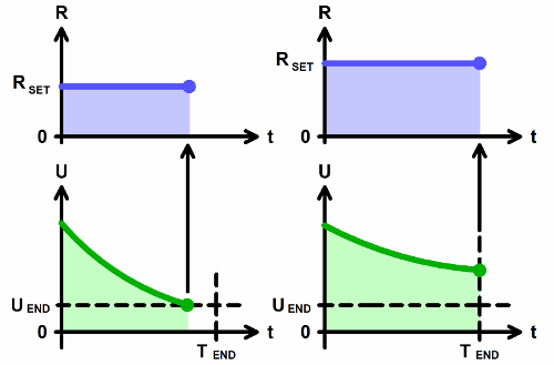
Discharge at constant resistance
designed to maintain a given battery discharge resistance. With a decrease in voltage, the current will also decrease so that the ratio of voltage and current is equal to the specified.
Discharge at constant voltage
designed to hold the voltage at a given level after discharge. In this mode, the device simulates a powerful zener diode with a given stabilization voltage. The end of the step occurs when the current drops to a predetermined value, as well as after a predetermined time.
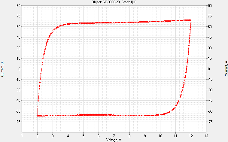
Voltage scanning mode
smoothly changes the voltage on the battery. The voltage changes from a given start value U1 to a given end value U2 at a given rate.
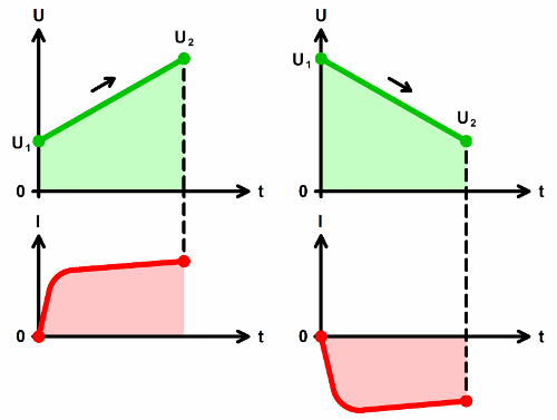
You can use a combination of the two voltage scanning modes in the cyclic part of the test program. This makes it possible to investigate chemical current sources by the method of cyclic voltammetry in the mode of a powerful potentiostat galvanostat.

Current scanning mode
smoothly changes the current through the battery. The current changes from the set start current I1 to the set end current I2 at a given speed.
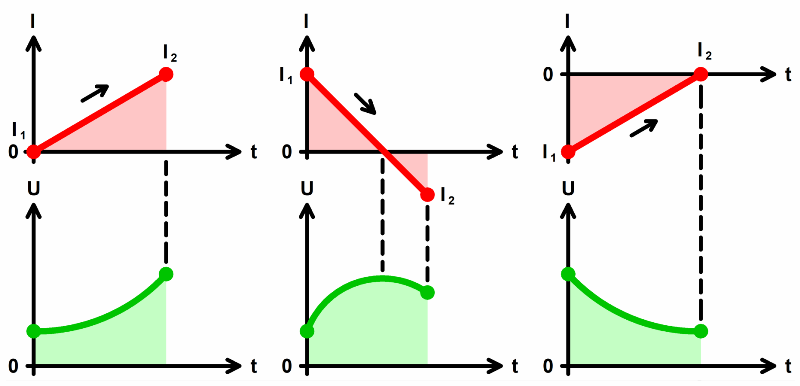
The currents I1 and I2 can be either positive (charge current) or negative (discharge current). In addition, one of the current values can be zero.
Power scanning mode
smoothly changes the power on the battery. The power changes from a given initial power P1 to a given final power P2 at a given speed.
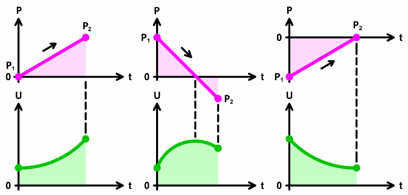
The powers P1 and P2 can be either positive (charge power) or negative (discharge power). In addition, one of the power values can be zero.
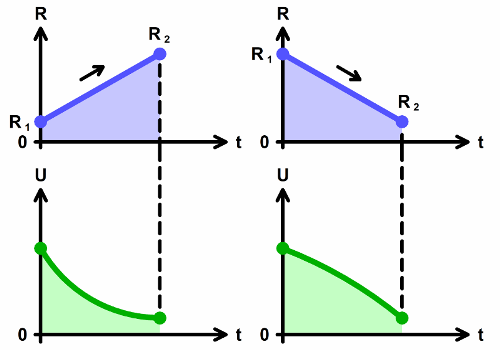
Resistance scanning mode
smoothly changes the load resistance for the battery. The resistance changes from the initial value R1 to the final value R2 at a given speed.
Current pulse mode
supplies alternating current pulses of set values I1 and I2 through the accumulator. The current I1 applies for the set time T1, while the current I2 applies for the set time T2. The currents I1 and I2 can be either positive (charge current) or negative (discharge current).
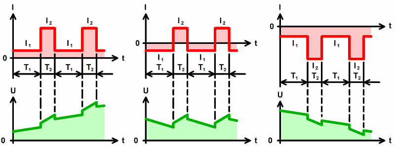
The step ends when the battery voltage reaches the specified value, as well as after the specified time.
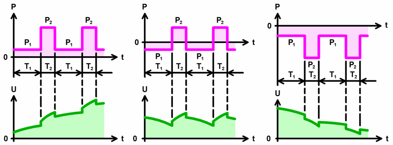
Power pulses mode
supplies alternating power pulses with preset values P1 and P2 to the battery. Power P1 applies for a given time T1, while power P2 applies for a given time T2. The powers P1 and P2 can be either positive (charge power) or negative (discharge power).
Resistance modes
supplies alternating impulses of resistance of preset values R1 and R2 to the battery. Resistance R1 applies for a given time T1, while resistance R2 applies for a given time T2.
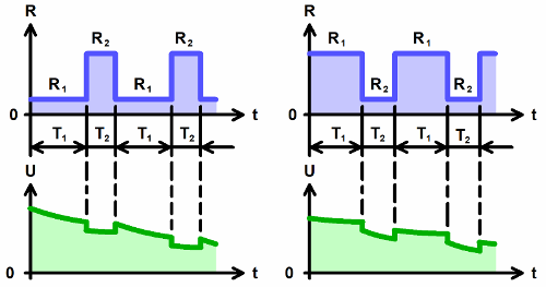
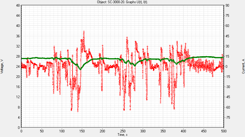
Table mode
A separate class of operating modes for analysers of batteries is work according to the tables of current, power and resistance.
In these modes, the battery analyzer operates according to previously prepared and selected tables. Tables must contain two columns. The first column is time. The second is the required values of current (power or resistance), which should be at this time.
The table modes simulate battery performance in a wide variety of applications.
For example, simulating the operation of an electric car battery when the car is moving in an urban driving cycle, or in any other.
The table modes will be useful for simulating the operation of batteries, for example, in:
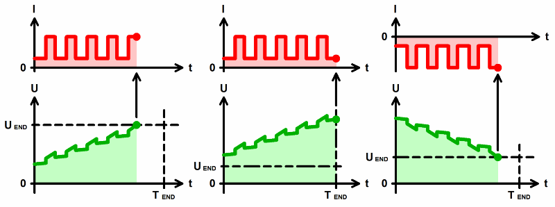
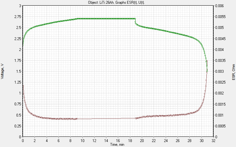
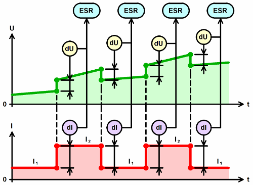
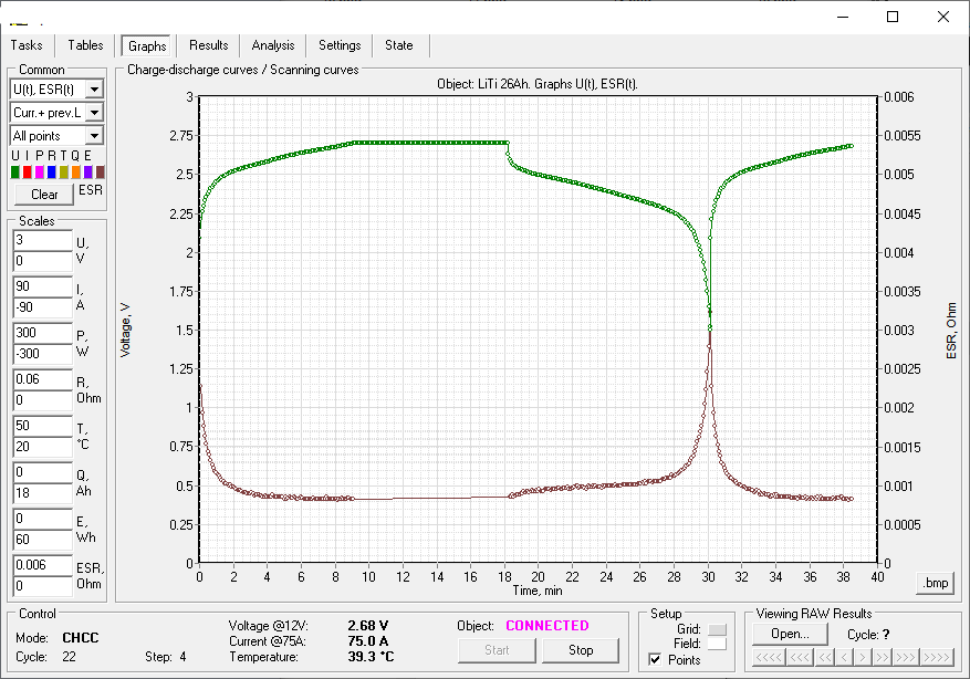
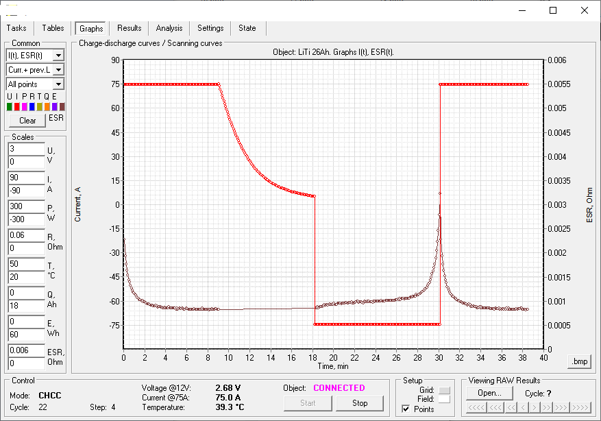
Measurement of the equivalent series resistance of the battery
Potentiostat.fi battery analysers are capable of measuring battery equivalent series resistance (ESR).
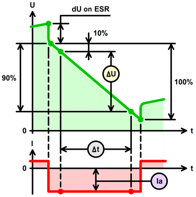
There are few ways for ESR measurement. The most accurate way is to interrupt the charge and discharge current with a specified period for a specified time.
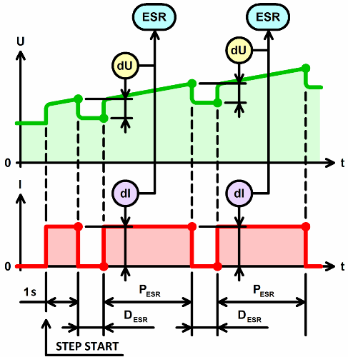
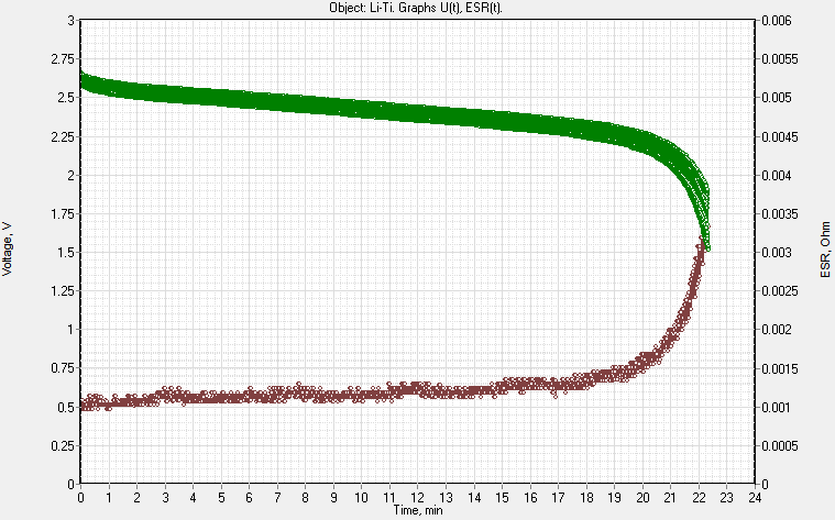
This measurement mode allows you to plot the dependence of the ESR of the battery on the degree of its charge or discharge.
ESR measurement also occurs when changing pulses of current, power or resistance in the pulse modes.
Measuring of capacitance of supercapacitors
Among other things, ACK analysers are capable of measuring the electrical capacitance of supercapacitors, in Farads. The capacitance is measured at the constant current discharge step.
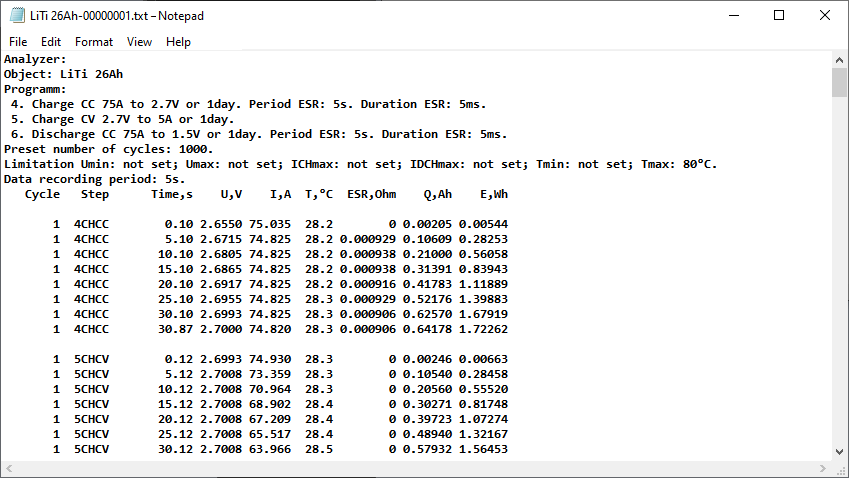
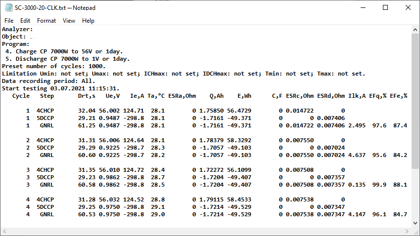
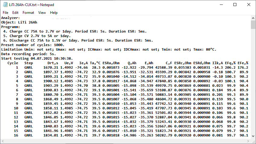
Measurement result files
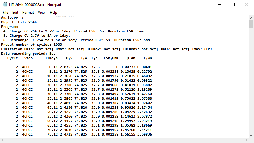
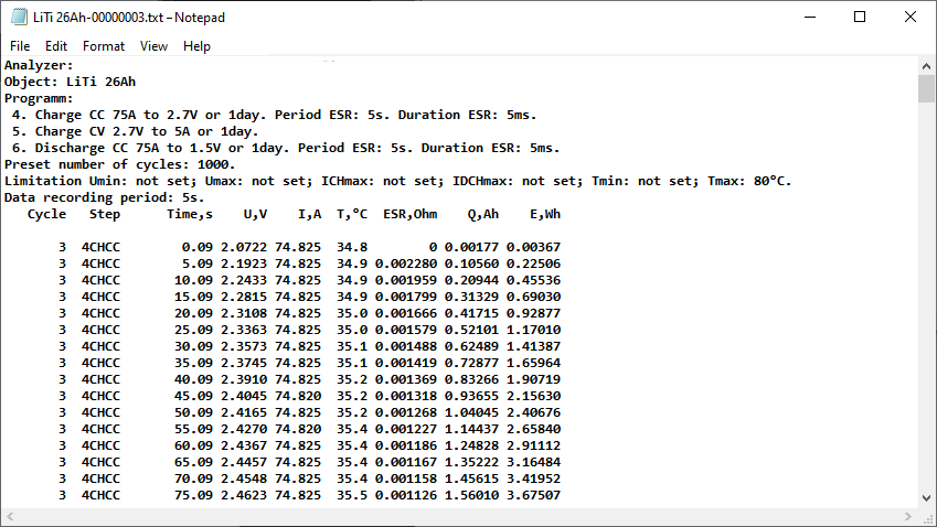
The end result of the work of the Potentiostat.fi battery analysers are text files of the measurement results. The analyzer stores two types of result files. Several files of primary data, as well as one general file of summary measurement results.
Primary data files are saved one for each charge discharge cycle performed. If the test program requires a large number of charge-discharge cycles, you can customize results files thinning. In this case, the primary data files will be saved, for example, only for every 10th cycle.
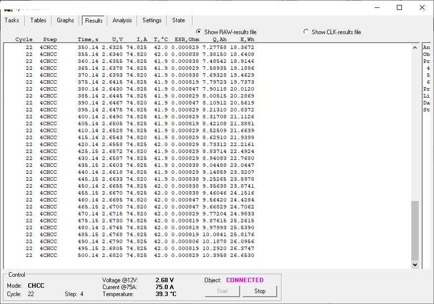
Primary data files
contain the following parameters:
Based on the measurement results from the primary data files, there can be:
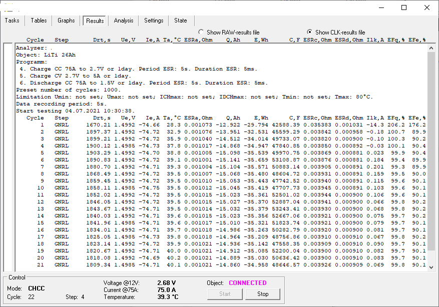
Summary measurement result files
contain processed data. Each line of the summary results file describes summary data for a whole step, or for a whole cycle.
The lines of the summary measurement results file contain
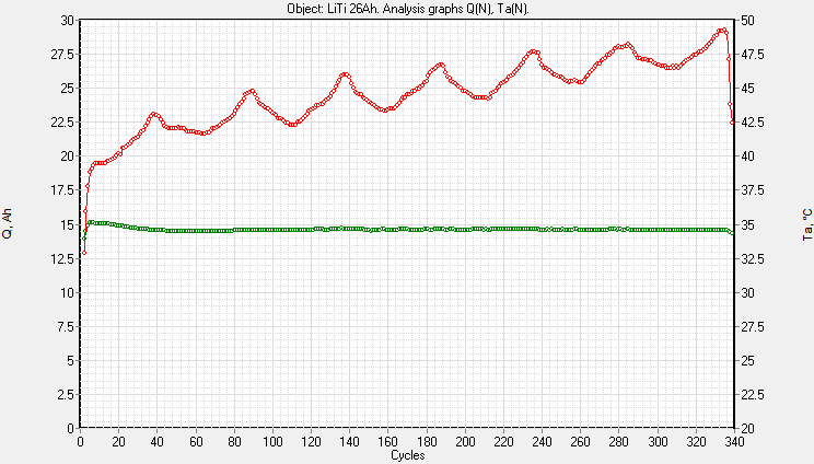
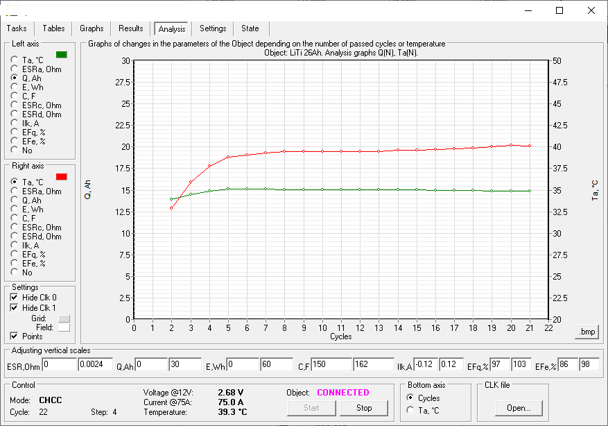
The software can generate the following types of graphs based on the summary measurement results:
This is very useful, for example, for cycle-life testing of batteries or climatic testing of batteries.
Software for battery analysers Potentiostat.fi
Battery analysers work in connection with special software. The oftware is versatile. It is suitable for working with all modifications of Potentiostat.fi devices. The software contains several parts. These parts help to:
Tasks
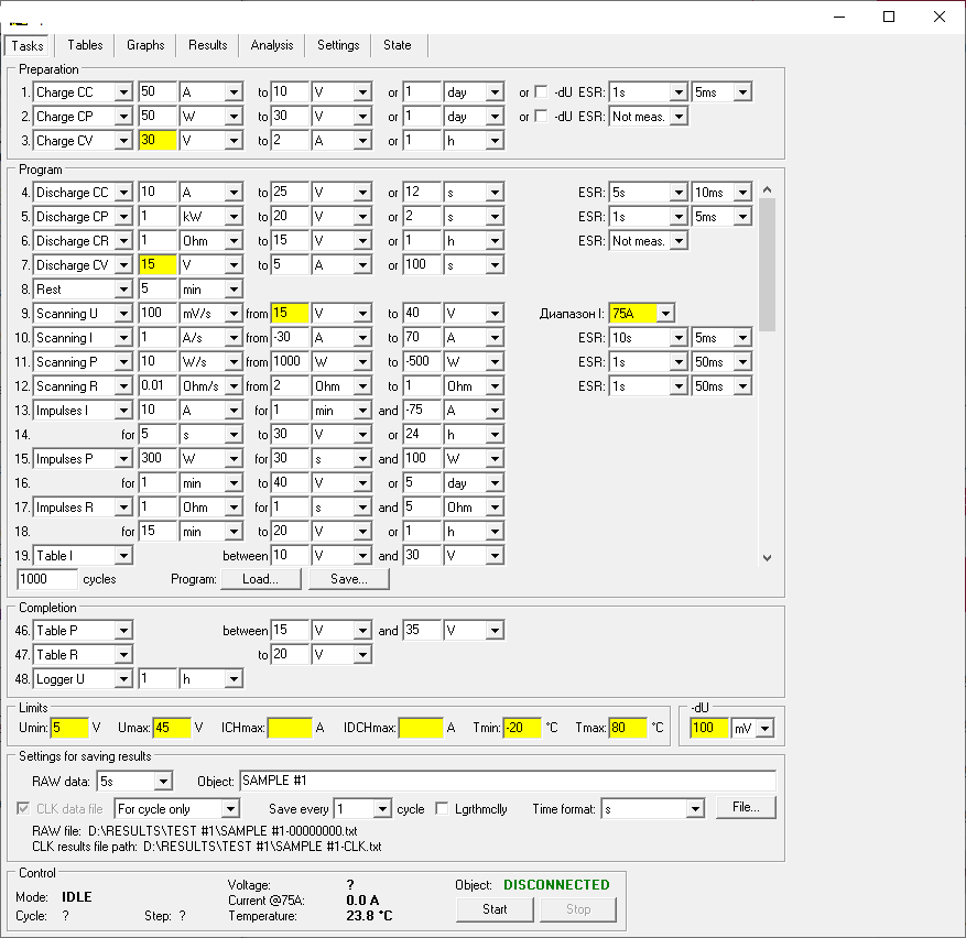
On the Tasks page you should:
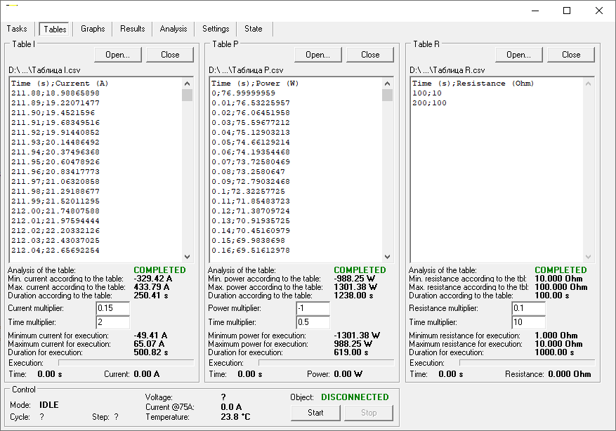
Table
is intended for selection and adjustment of tables for operating modes according to tables. Here you can select the individual table files for the operating modes according to the current, power and resistance tables. The user can quickly adjust the time range, as well as the range of the parameter in the table with the required multipliers.
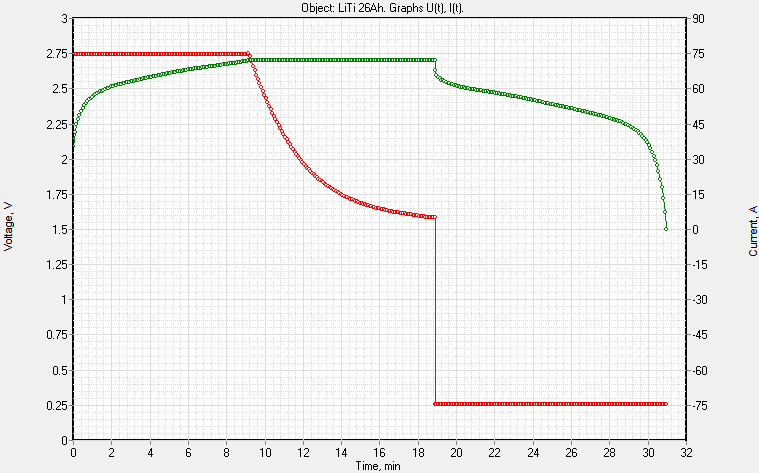
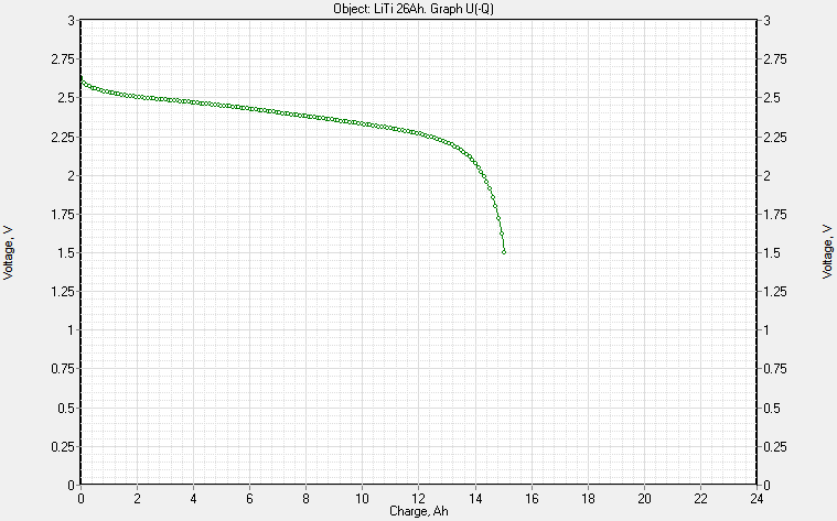
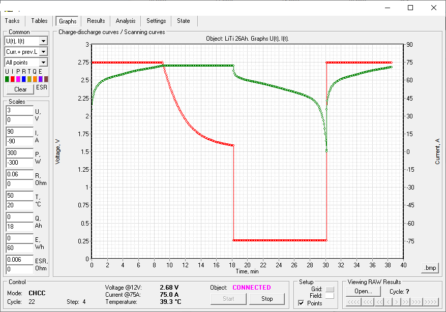
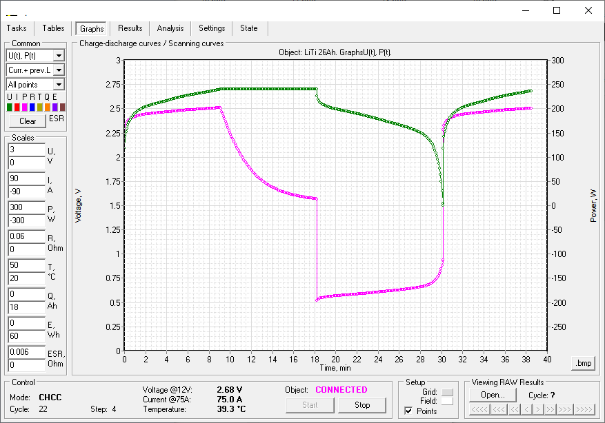
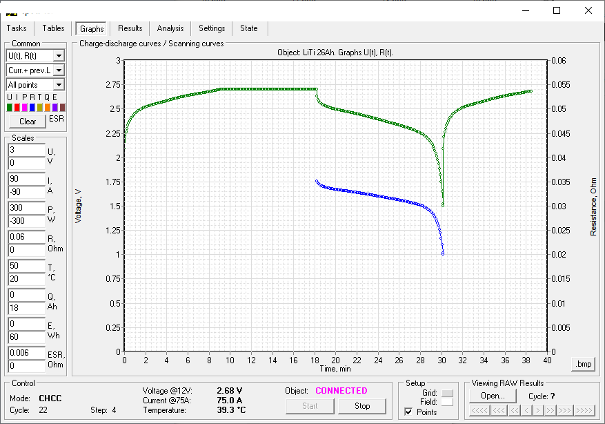
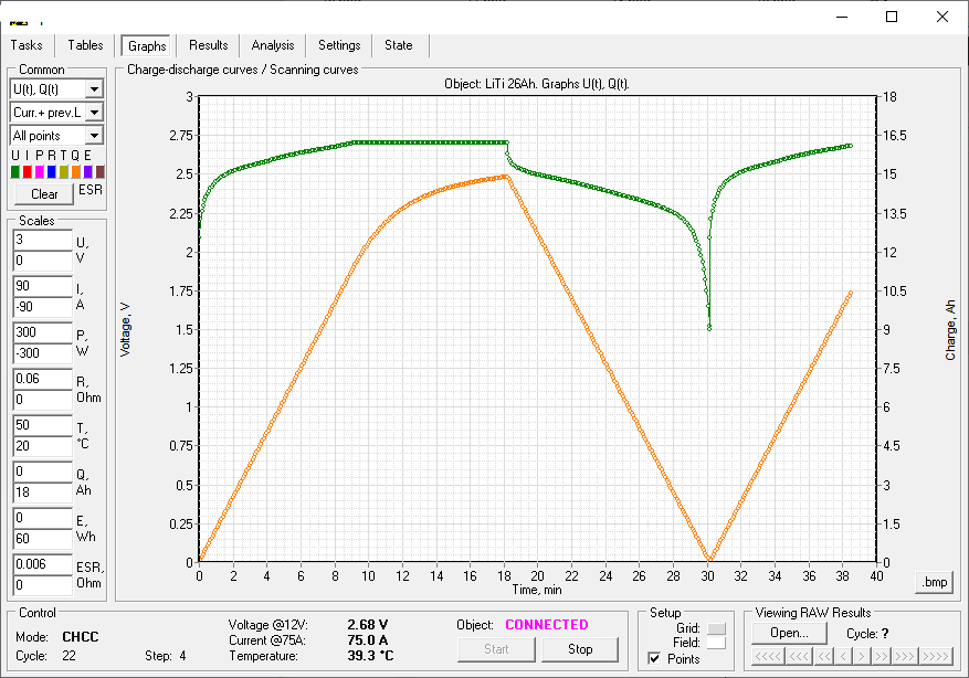
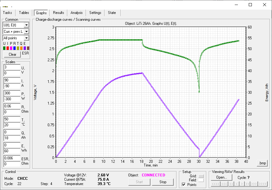
Graphs
displays the graphs of the charge discharge of tested battery. Here you can see changing parameters of battery in various combinations, for example:
Results
allows you to observe the formation of files of measurement results.
Analysis
displays graphs of changes in battery characteristics depending on the following parameters:
The page allows you to visually observe the change in the characteristics of the battery during cycle-life tests, as well as during climatic tests.
Settings
is intended for setting up a connection to a battery analyzer or to several analysers in their parallel operation.
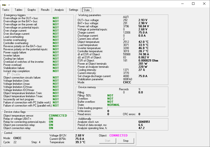
Status
provides detailed information on the operation of the ACK battery analyzer. In addition, information is provided on various emergency events that may occur during the tests.
Autonomous operation of battery analysers Potentiostat.fi
The Potentiostat.fi battery analysers have built-in memory. The memory halps to save the measurement results in case the connection with the computer becomes temporarily unavailable.
When the connection is restored, the analyzer transfers all the accumulated data to the computer. Then the software saves the data to the files of the measurement results.
As a result, the built-in memory enables the battery analyzer to operate autonomously for some time after starting the test. This allows you to turn off your computer at night, as well as on weekends or holidays.